Assembling the Tool Items
Additional components, such as Adaptors and Holders, can be added to the Tool Item in several ways by using either automatic or manual methods.
Manual method
You can manually add Adaptors and Holders using one of the following:
- Use the Library Toolbar and Selection Pane to select from the available SolidCAM Components
Use the Tool Item Manager right-click commands
Automatic method
It is also possible to have the system automatically add the Adaptor and Holder upon adding your Cutter component to the Part Tool Table. To do so, enable Auto add the Adaptor and Holder in the ToolKit Settings.
If you are not using the Auto add the Adaptor and Holder setting, the steps to add these components to the Tool Item and define their properties are as follows:
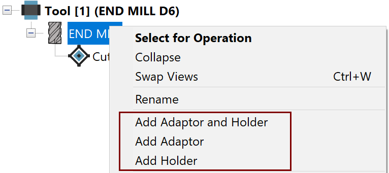
In the Tool Item Manager, right-click the Tool Item and choose the appropriate command to add the desired component(s).

For example, if you select Add Adaptor and Holder from the appearing shortcut menu, the components are simultaneously added to the Tool Item tree as shown.

|
The Tool Item tree structure represents the actual arrangement of components when physically assembled and mounted on your CNC-Machine. |
When the Tool Item commands are used to add a component, it is considered EMPTY and you are prompted to define its geometry.
|
If Adaptor Type is specified in the *.vmid file of your CNC-Machine, the Adaptor component is automatically defined as such in the Tool Item tree.
|
.png)
Define the Adaptor/Holder geometry.
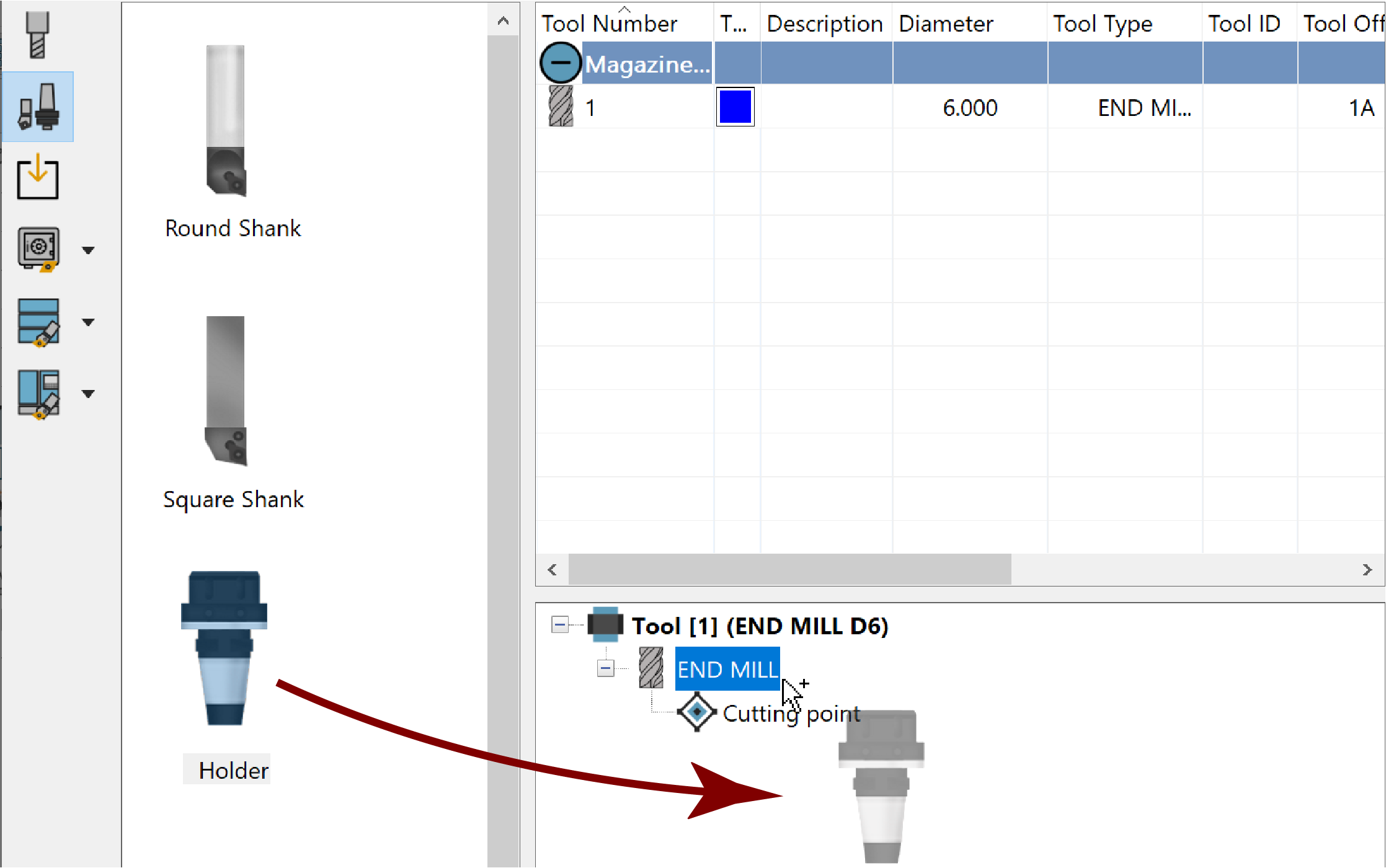
Automatically loaded in the Selection Pane is SolidCAMComponentsLib or the Default Library selected in the ToolKit Settings, which facilitates defining the component geometry.

In the Selection Pane, expand the Adaptors and Holders folders as needed and double-click the desired component or simply drag & drop it into the Tool Item window.

The EMPTY component will be replaced by the one you have chosen.
If the included components do not suit your needs exactly, new ones can be defined or the provided ones can be edited.
After defining the Adaptor/Holder geometry, use the Data Toolbar and Page as needed to define the remaining properties such as the Connection Data.
![]() Connection
defines the Mounting and Joint CoordSys positions of components in the
Tool Item assembly.
Connection
defines the Mounting and Joint CoordSys positions of components in the
Tool Item assembly.
The Mounting position of each component is affixed/connected to the CoordSys position of the higher component in the Tool Item tree.
As shown in the example below, the Holder C5 SRKIN 16X80 is mounted to the Station CoordSys position of the Spindle and the END MILL is mounted to the Joint_1 CoordSys position of the Holder C5 SRKIN 16X80.

(Advanced View shown for illustrative purposes)
If necessary, you can modify the default positions with linear and rotational movements or with planar movements. For example, a position can be moved along the X-, Y- and Z-Axes by entering a value in the corresponding X, Y and Z fields or by scrolling your mouse wheel to change the value gradually.

Such movements can be seen using the available ToolKit Visualization Tools.
Related Topics