3D Constant step over machining parameters
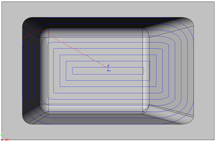
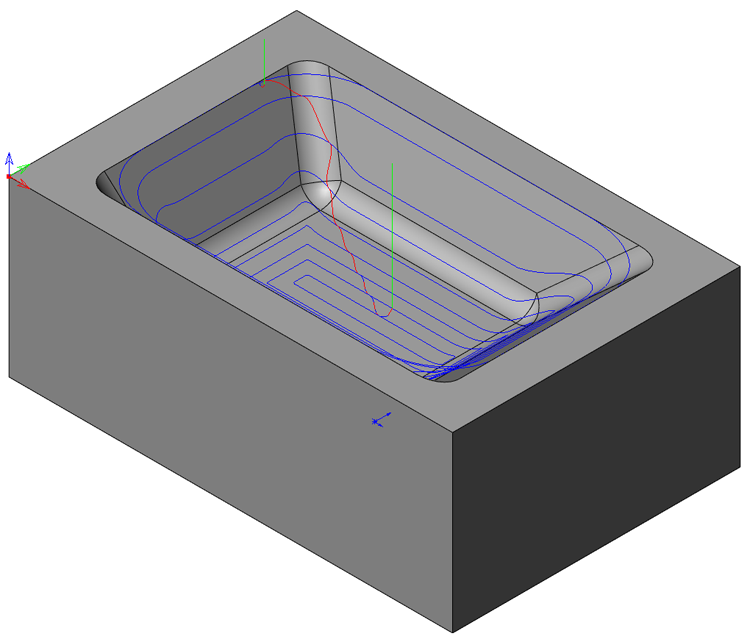
3D Constant step over machining enables you generate 3D tool path on the CAM-Part surfaces. The passes of the tool path are located at a constant distance from each other, measured along the surface of the model.
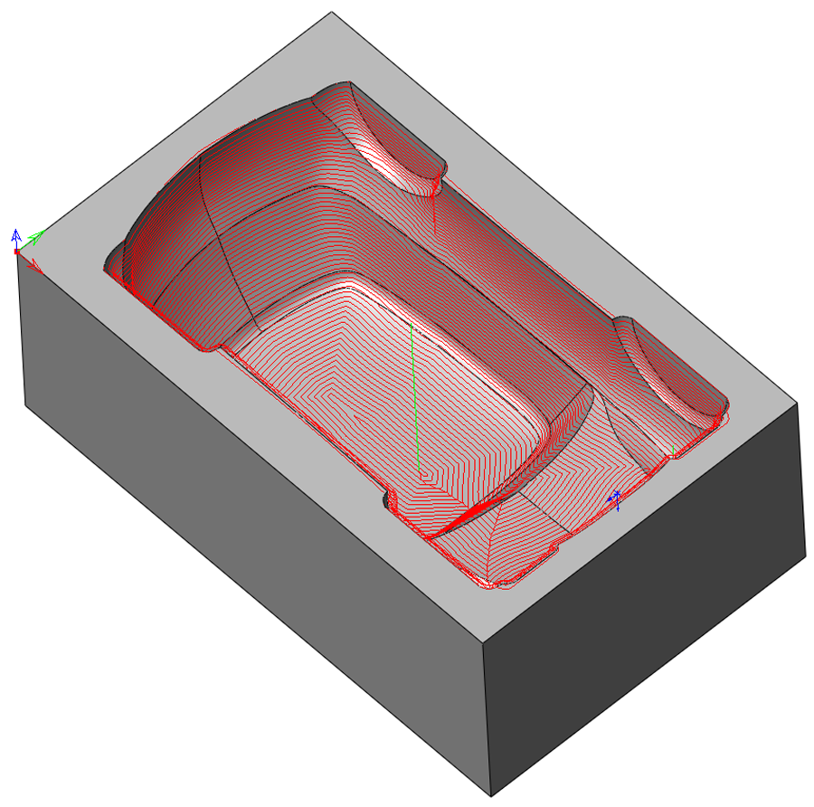
This is an ideal strategy to use on the boundaries generated by rest machining or in any case where you want to ensure a constant distance between passes along the model faces.
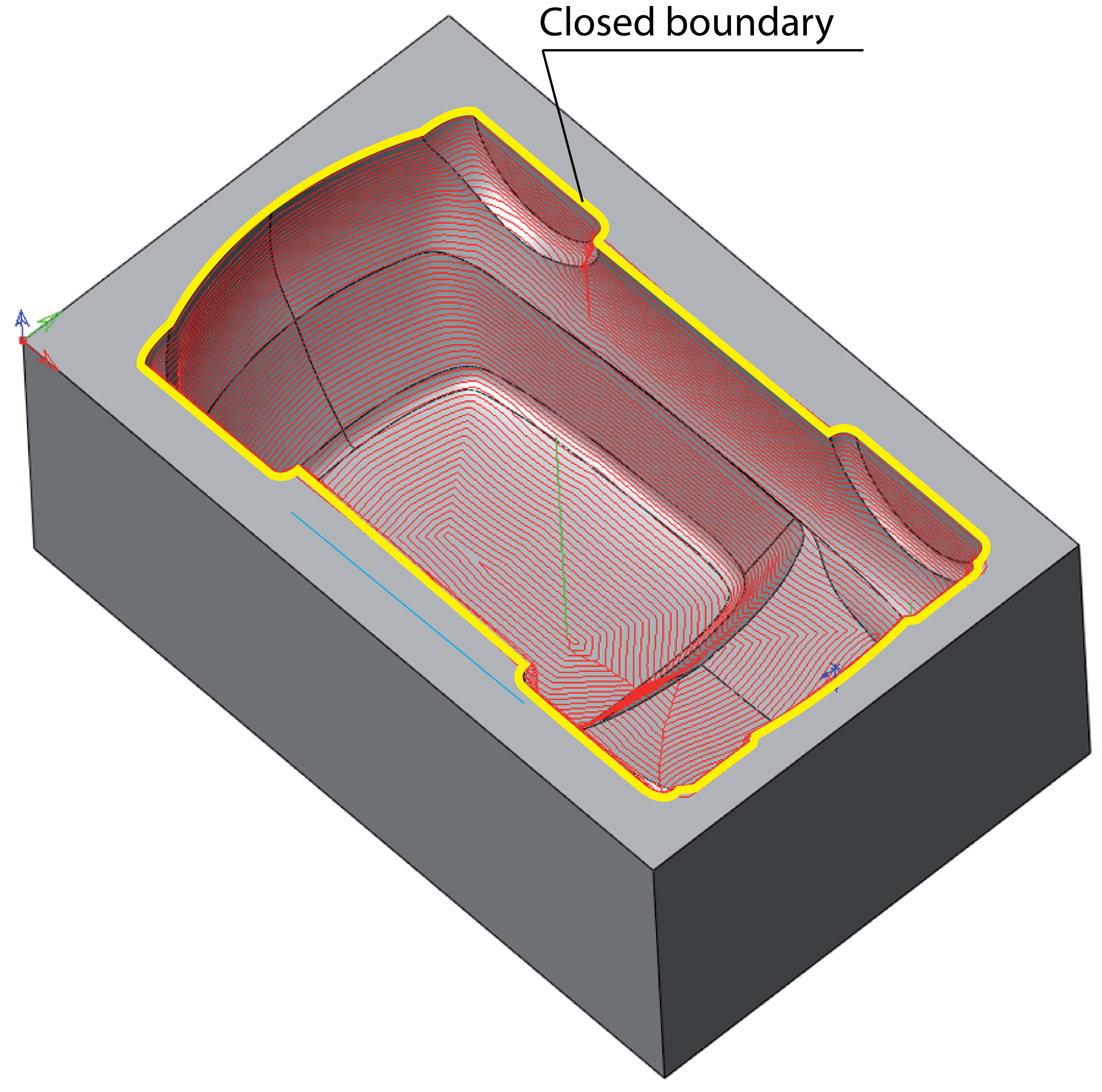
Constant surface Step over is performed on a closed profile of the Drive boundary. SolidCAM creates inward offsets from this boundary.
Step over
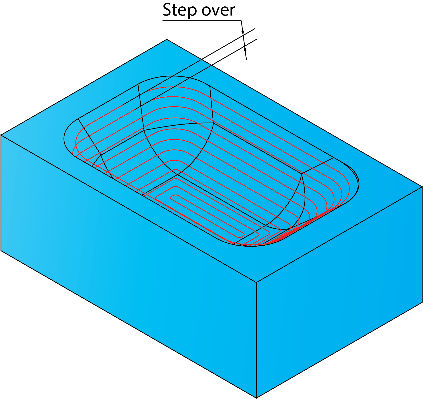
This parameter enables you to define the distance between cutting passes. In 3D Constant step over machining, the Step over value is calculated in such a way that all passes are equidistant along the surface.
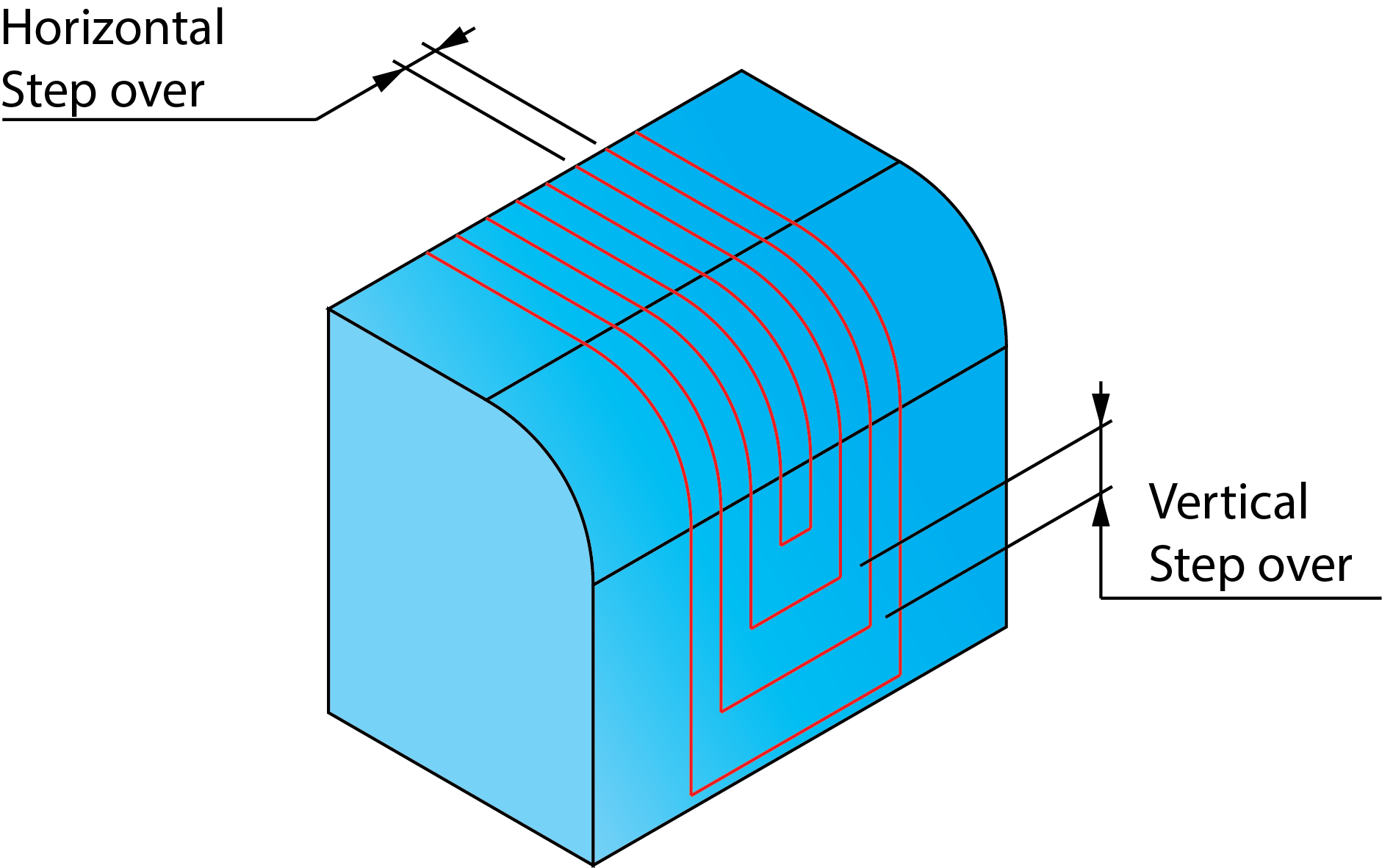
The Horizontal and Vertical Step over parameters determine the distance between passes. The two Step over types relate to the direction in which the Step over is being measured. Where passes are offset horizontally, the Horizontal Step over distance is used while for passes that are offset vertically, the Vertical Step over distance is used. Where the step direction is neither vertical nor horizontal, the average of the two values is used.
Limit offsets number to
The Limit offsets number to parameter enables you to limit the number of offsets of a drive boundary profile. Select the Limit offsets number to check box and set the offsets number.
Adaptive variable side step
If the Adaptive variable side step check box is selected, step over will be taken from the horizontal plane only, that is, a 2D offset. With this option, only the Horizontal Step over value is used, the Vertical Step over value is not relevant.
You can see from the illustration above that using this option on this model creates only few passes on steep areas since the spacing is calculated only along the horizontal plane; using this option is therefore not recommended for such models.
Related Topics