Spiral machining parameters
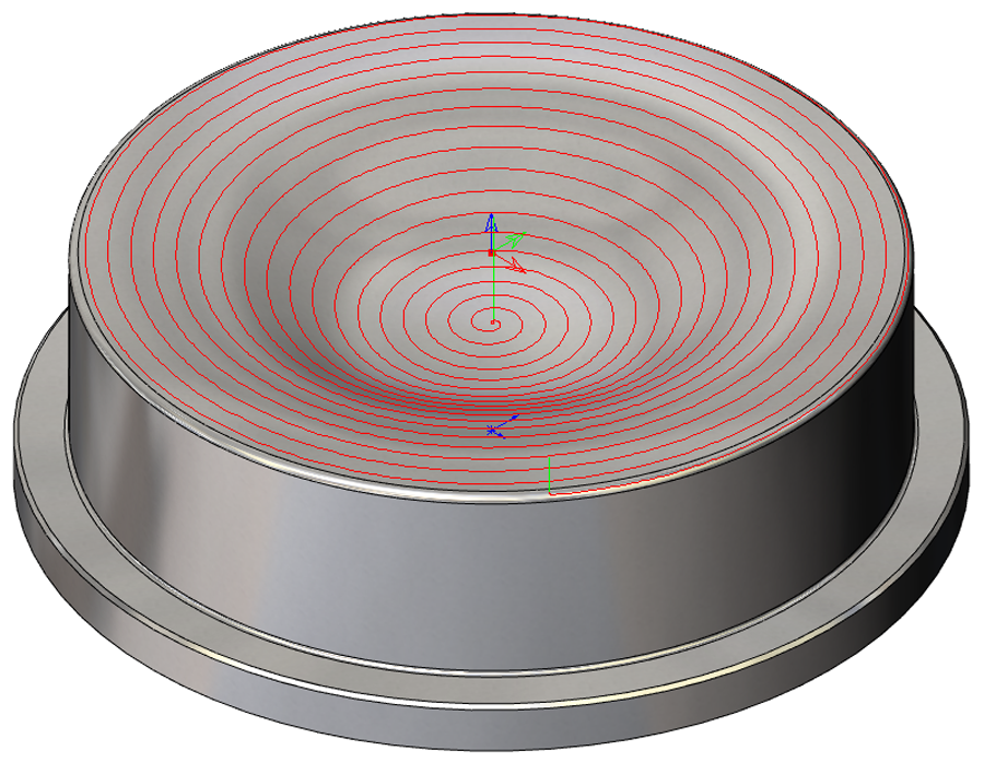
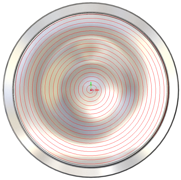
The Spiral machining strategy enables you to generate 3D spiral tool path over your model. This strategy is optimal for model areas formed by revolution bodies. The tool path is generated by projecting a planar spiral (located in the XY-plane of the current Coordinate System) on the model.
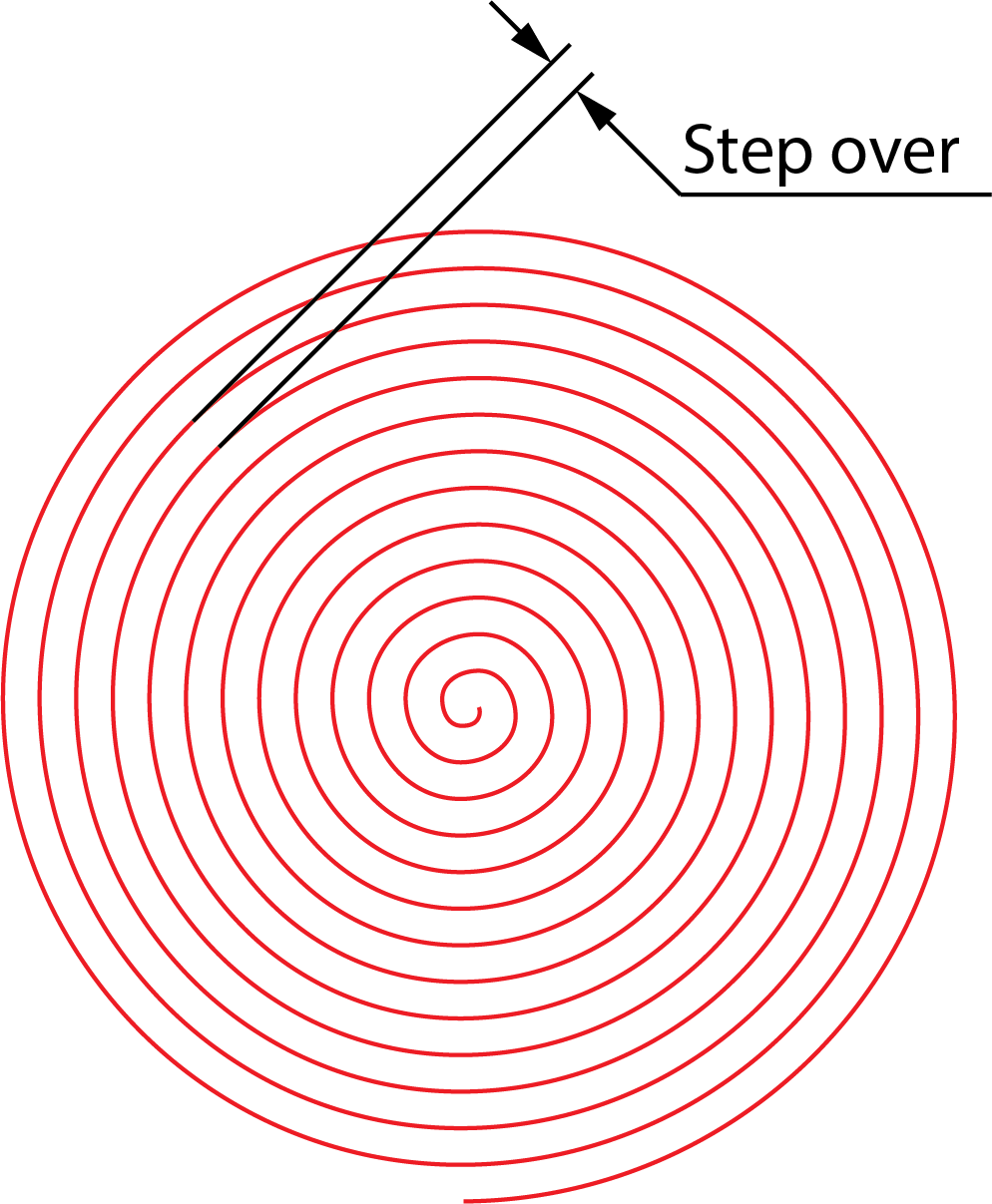
Step over
The Step over parameter defines the distance between two adjacent spiral turns in the XY-plane of the current Coordinate System.
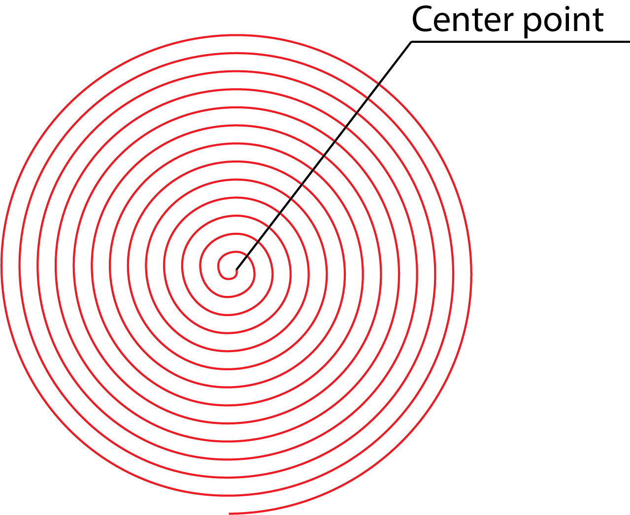
Center
You have to specify the XY-position of the center point of the spiral. The spiral tool path is calculated from this point, even if it does not actually start from there (minimum radius may be set to a larger value).
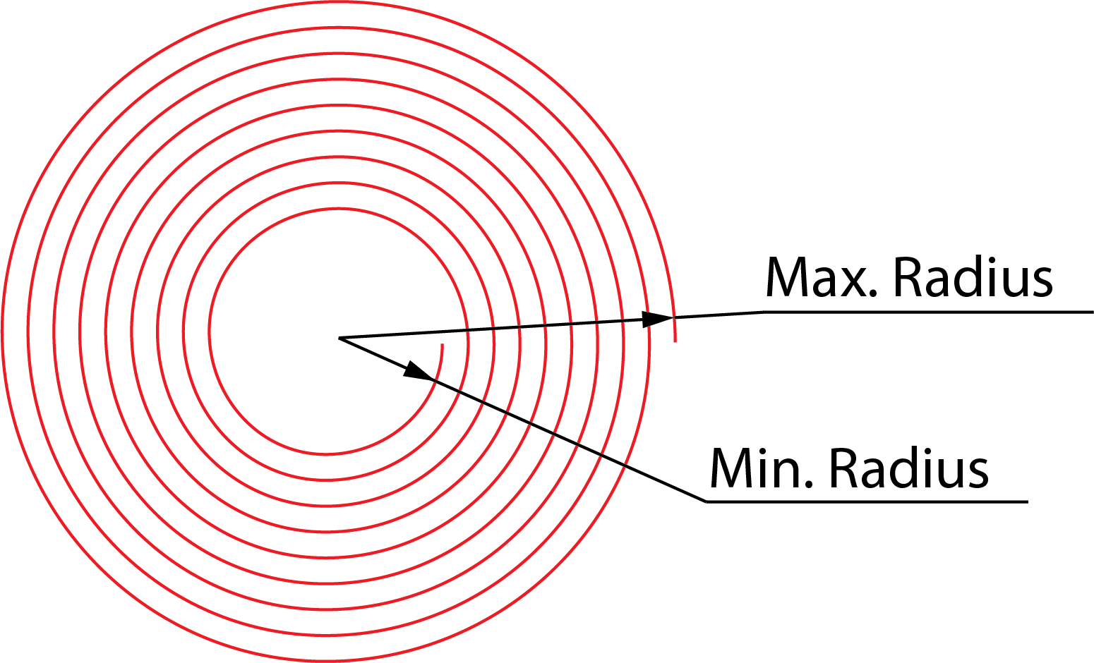
Radii
Define the area to be machined by the spiral by setting the minimum and maximum Radii. If the spiral is to start from the center point, set the Minimum Radius value to 0. When the spiral is to start further from the center, enter the distance from the center point by setting the Minimum Radius to a higher value. Control the overall size of your spiral with the Maximum Radius value.
You can define the radii by entering the values or by clicking the buttons and picking points on the model. The X- and Y-coordinates of this point are displayed in the Select a coordinate dialog box.
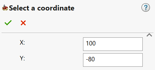
When this dialog box is confirmed, the radius value appears in the appropriate edit box calculated as the distance from the defined center point of the spiral pattern of passes.
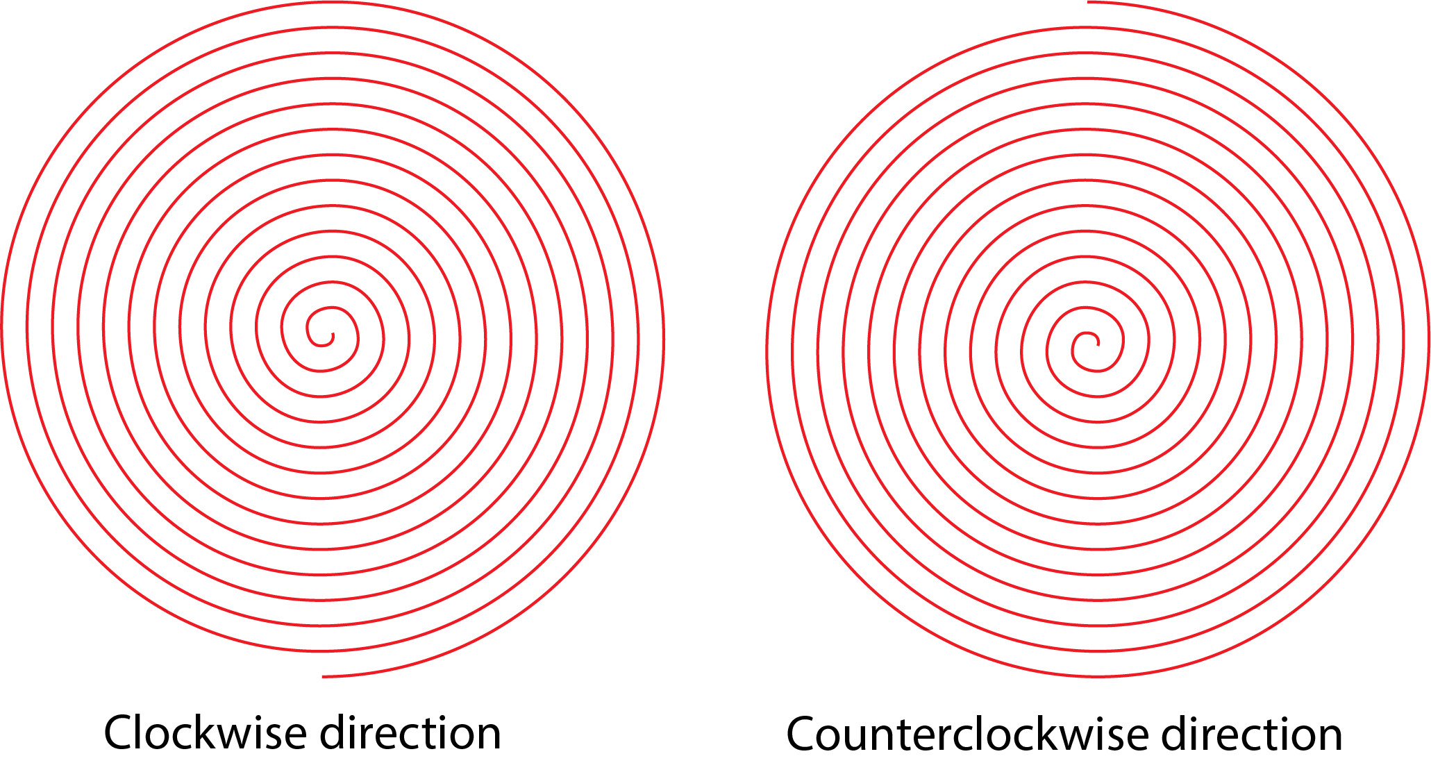
Clockwise
This option enables you to define the direction of the spiral. When this check box is selected, SolidCAM generates a spiral tool path in the clockwise direction. When this check box is selected, SolidCAM generates a spiral tool path in the counterclockwise direction.
Related Topics
- 3D Constant step over machining parameters
- Contour roughing parameters
- Hatch Roughing parameters
- Helical machining parameters
- Linear machining parameters
- Morphed machining parameters
- Offset cutting parameters
- Common Parameters
- Pencil Milling parameters
- Radial machining parameters
- Rest Roughing parameters
- Strategy parameters