Introduction
Complete information about the CAM-Part is displayed in the SolidCAM Manager.

The SolidCAM Manager contains the following headers:
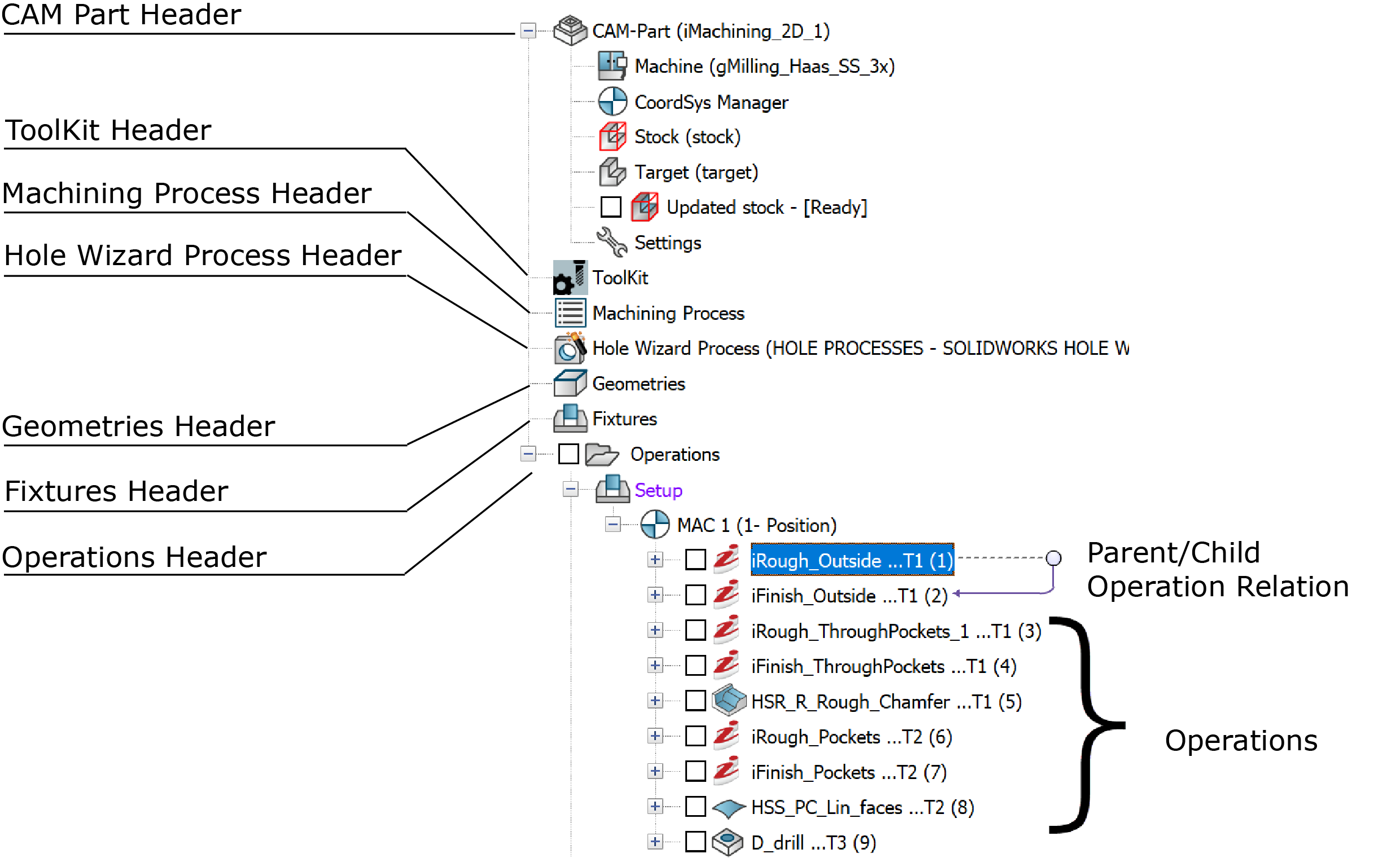
This header displays the name of the current SolidCAM CAM-Part. Right-click the CAM-Part header to activate the CAM-Part menu and manage your CAM-Parts. The Machine, CoordSys Manager, Stock, Target and Settings sub headers are located under the CAM-Part header. Double-click the CAM-Part header to display the Milling Part Data dialog box.
This header displays the name of the current Part Tool Library. Right-click the ToolKit header to activate the menu and manage the Tool Libraries. Double-click the ToolKit header to display the TOOLKIT dialog box.
This header displays the name of the current Machining Process Table. Right-click the Machining Process header to activate the menu and manage the MP Tables. Double-click the Machining Process header to display the Current Machining Processes Table.
This header displays all the SolidCAM geometries that are not used in the operations. Click the "+" icon adjacent to the Geometries header to get the list of these geometries. Right-click the Geometries header to display the geometries managing menu. Right-click each geometry name to open the relevant menu. Double-click a geometry name to display the selected geometry.
This header displays all the fixtures that are not used in the operations. Click the "+" icon adjacent to the Fixtures header to display the list of these fixtures. Right-click the Fixtures header to display the fixtures managing menu. Right-click each fixture name to open the relevant menu. Double-click a fixture name to display the selected fixture.
Operations header
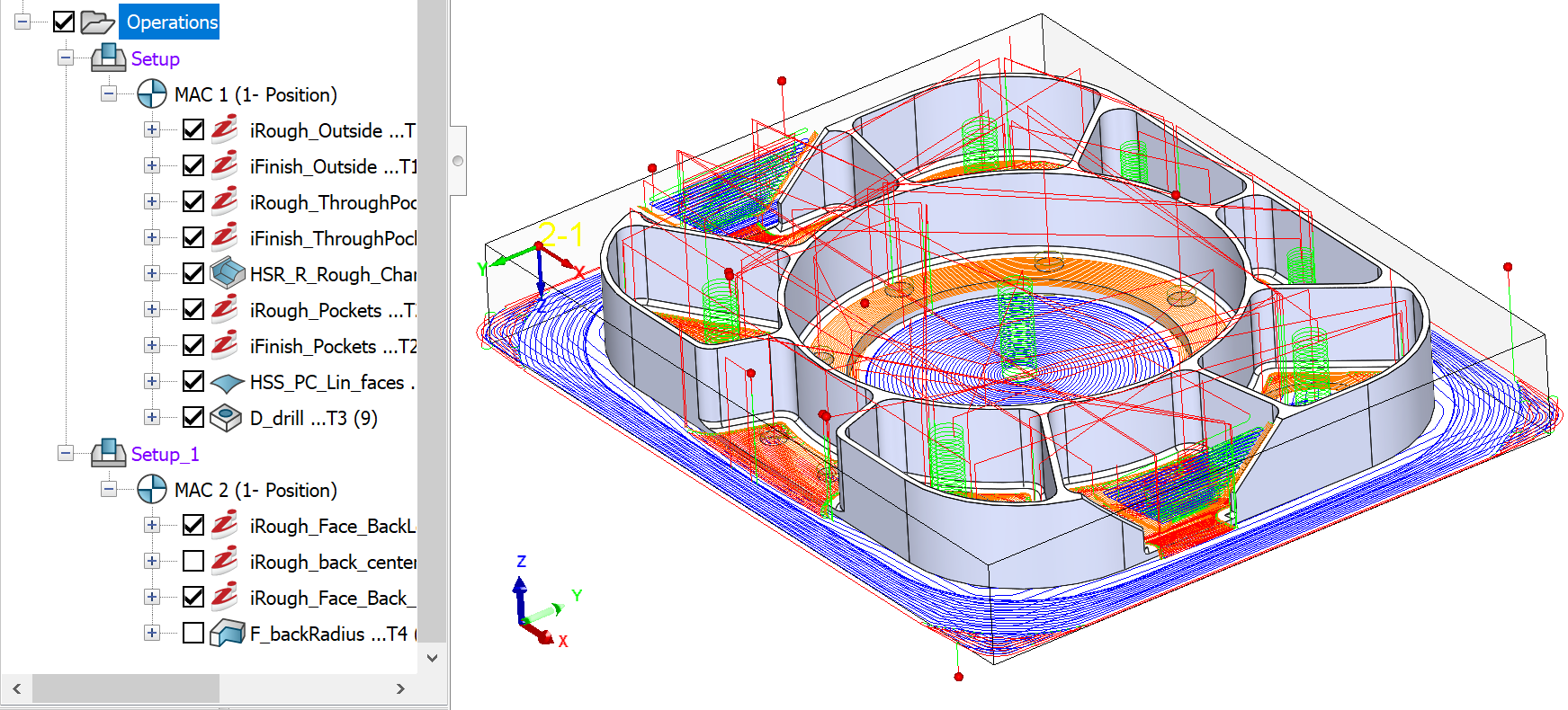
This header shows you all the SolidCAM Operations. Right-click the Operations header to view the operations managing menu. Right-click each operation name to view the relevant menu.
Double-click an operation name to edit operation parameters with the specific operation dialog box. If you double-click an operation name when the other operation dialog box is open, the previous dialog box will close automatically.
The check box near the Operations header enables you to display the tool path for all the CAM-Part operations directly on the SOLIDWORKS model from the CAM Manager.
The check box near the CAM Operations enables you to display the tool path directly on the SOLIDWORKS model.
Parent/Child Operation Relation - You can display the Parent/Child relation of a selected operation. A Parent/Child feature is an existing feature upon which others depend. This is displayed by the connector lines and arrow.
To view Parent/Child relation, right-click Operations Manager, click CAM tree View, and select Show/Hide Related Operations arrow.
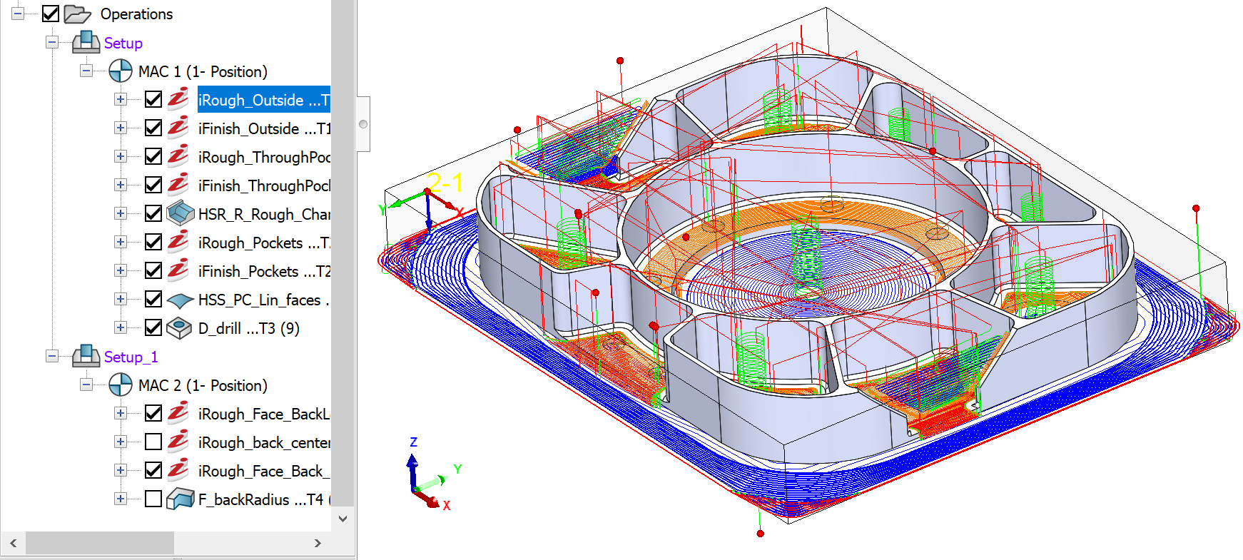
Highlight Tool path - When the process of calculating an operation is completed, the check box before the operation is automatically selected and the tool path is displayed on the SOLIDWORKS model. To highlight a particular tool path, select the Operation from the Operations Header. The tool path for that particular operation is displayed in bold on the SOLIDWORKS model.
 |
 |
Operation Not Selected |
Operation Selected |
Special symbols
CAM tree entities can use special symbols and conventions.