Adding a new Tool Item
At the Operation stage, the availability of Cutter Components [on the Toolbar] and corresponding Cutter/Tool Types [in the Selection Pane] are determined by the CAM-Part type and Operation type respectively. In the following example, a Milling CAM-Part is used.
The steps to add and define a new Tool Item using SolidCAM Components are as follows:
- In the SolidCAM
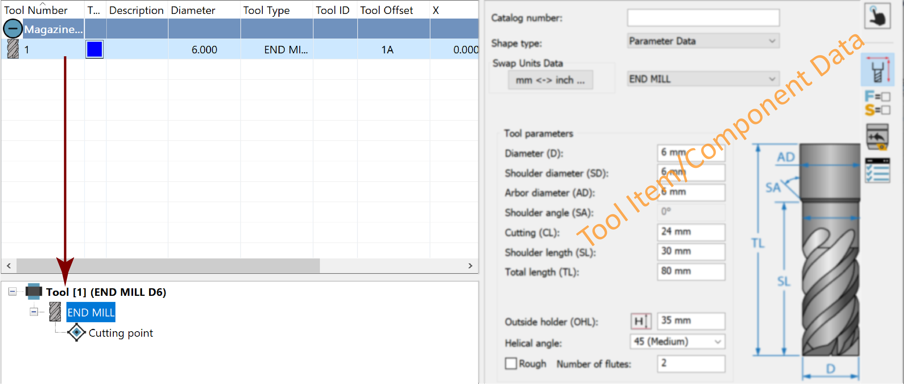
Manager, double-click the ToolKit header
 . All
tools defined for this CAM-Part appear in the Tool Table window for
viewing and editing.
. All
tools defined for this CAM-Part appear in the Tool Table window for
viewing and editing. - On the Toolbar, choose the Cutter Components you want displayed in the Selection Pane.

- In the Selection Pane, double-click the desired Cutter (Tool Type) or drag & drop it into the Tool Table window.

|
Right-click on the Tool type and select the mounting position of the Tool. In the Part Tool Table, the Tool is placed under the mounting position selected. In the example below, the End mill is mounted on the 'Magazine Spindle'.
|

Upon adding your Cutter to the Part Tool Table, the corresponding Tool Item is created and displayed in the Tool Item Manager.
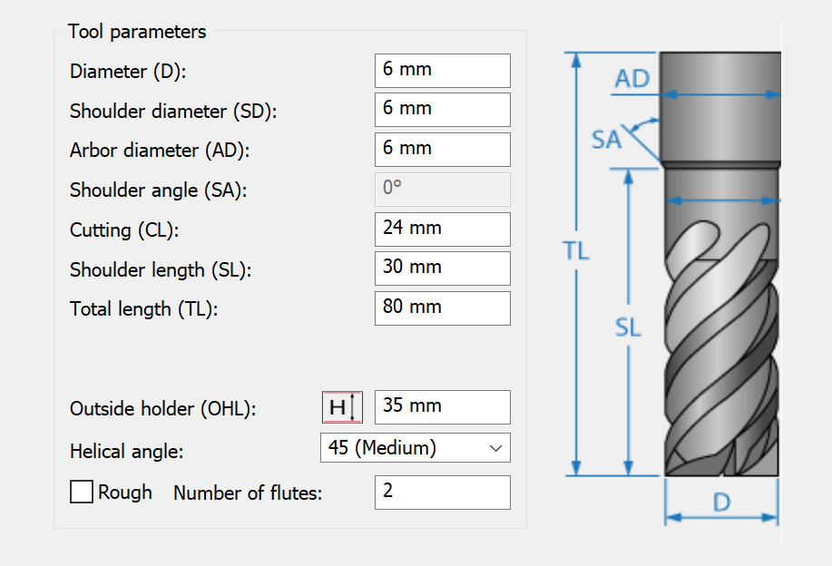
- Define the Cutter geometry.
![]() Topology
is the default selection on the Data
Toolbar, prompting you to specify the Cutter dimensions in the
Data Page.
Topology
is the default selection on the Data
Toolbar, prompting you to specify the Cutter dimensions in the
Data Page.
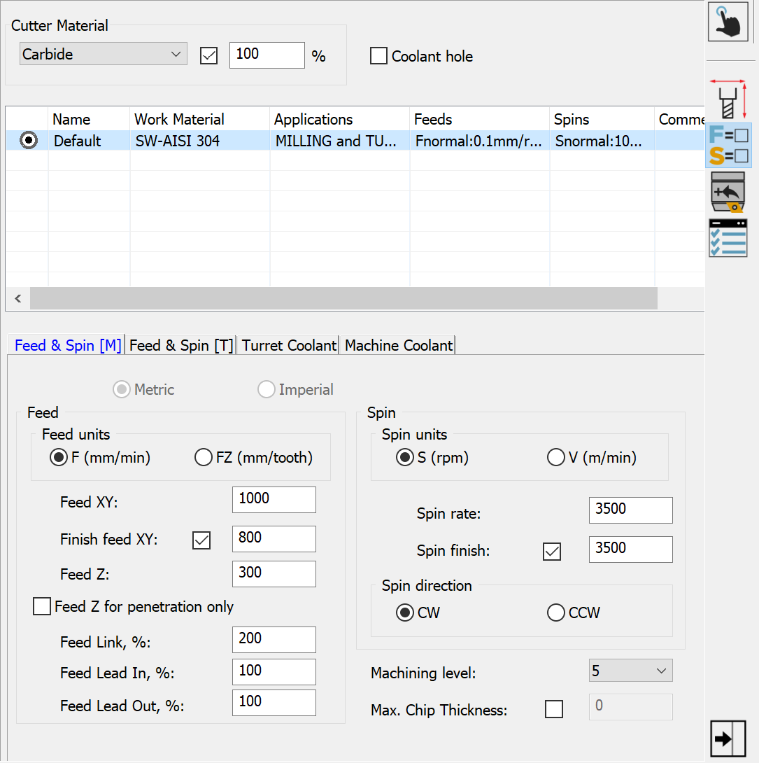
- After defining the Cutter geometry, use the Data Toolbar and Data Page as needed to define the remaining properties such as the Feed & Spin data.
Related Topics