Geometry page
This page enables you to choose the appropriate Coordinate System and to define the Machining Geometry for the operation. Turning geometry can be defined by selecting wireframe elements or solid model entities such as faces, edges and vertices.
CoordSys
This button enables you to set a Coordinate System for the operation.
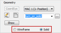
Geometry
This section enables you to start the geometry definition.
Click New  to
define a new geometry. Click Edit
to
define a new geometry. Click Edit
 to edit an existing geometry.
This option enables you to define the turning geometry by selecting wireframe elements using the Geometry Edit dialog box.
This option enables you to define the turning geometry by selecting model entities using the Geometry Selection on Model dialog box.
Browse
Browse Clicking this button displays the Browse Geometries dialog box that lists all the geometries of the type suitable for the chosen operation. When a geometry is chosen in this dialog box, it is highlighted on the model. |

|
Show
This button displays the model geometry in the SOLIDWORKS window.
Modify Geometry
This button enables you to edit the defined geometry using the Modify Geometry dialog box.
Partial machining
The Partial machining option is available only for Turning, Trochoidal Turning and Balanced Rough operations.
When the Partial machining check box is not selected, the machining is performed on the entire profile geometry.
When the Partial machining check box is selected, the machining of the geometry is performed by segments. The Data button displays the Partial Machining dialog box that enables you to define the parameters of partial machining.
|
The Data button is available only for the Rough and Finish only work types and when the geometry and the tool are defined. |
Related Topics