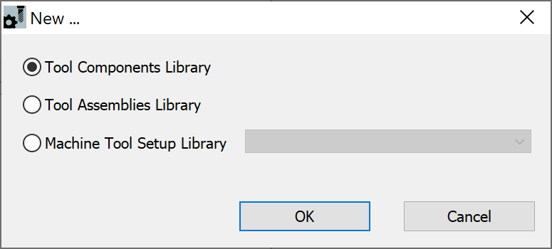
Tool Components Library ( *.tlv)
The first level of tool management offered by SolidCAM ToolKit is the Tool Components Library, which enables you to manage all your individual tool components, such as those typically stocked in your machine shop warehouse.
Customizable folders available to keep your component files organized in main library structure:
- Cutters
- Shanks
- Adaptors and Holders

In the following examples, the ToolKit Tool Libraries are created for use with a Mill-Turn CAM-Part.
For documentation purpose, a new Tool Components Library is defined by adding components from the available SolidCAM Components.
Defining a new Tool Components Library
The steps to define a new Tool Components Library are as follows:
- Start a new Tool Components Library using ToolKit standalone or one of the various options within SOLIDWORKS/SolidCAM.
Displayed is the TOOLKIT dialog box at the Tool Components Library level.

While most interface features are shared between all ToolKit Tool Libraries, the main difference in the Tool Components Library is the Vault Database that enables you to manage your components using an organized folder structure.
Using the Library Toolbar and corresponding Selection Pane, add the desired component to the appropriate folder in the Vault Database.
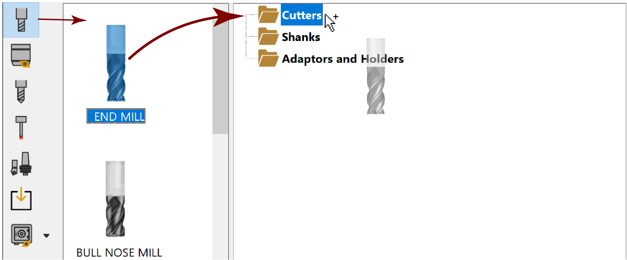
You can either double-click the component or simply drag & drop it into the folder in the Database window.
|
Double-clicking a component automatically adds it to a predefined folder (Cutters, Shanks or Adaptors and Holders), not to any nested folders (if defined). |
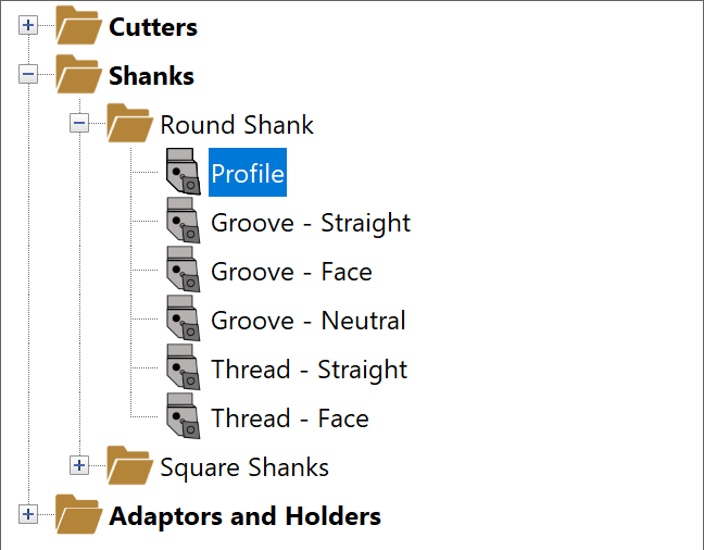
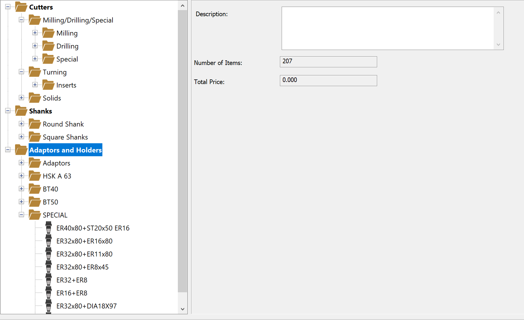
Tool Components Library folder structure
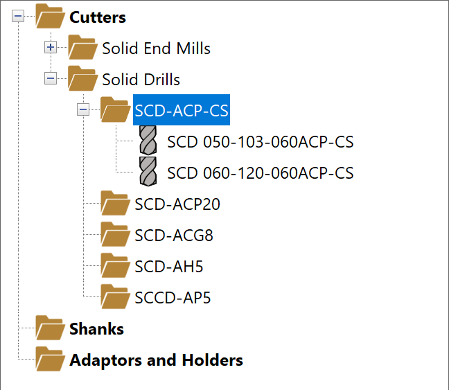
Currently, SolidCAM ToolKit provides you with three predefined folders- Cutters, Shanks or Adaptors and Holders.
The provided folders cannot be renamed, deleted, etc. However, you can manage any number of nested folders in the instance you want to organize your components into specific subcategories such as by type, manufacturer, application, and so on.
If you prefer creating a folder structure with Windows/File Explorer or if one is already defined on your computer, it can be easily imported using the Import Structure command in the right-click menu of the predefined folders.
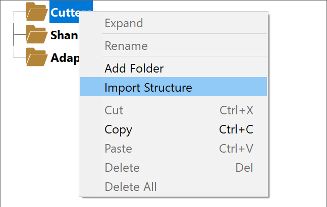
Imported folder structures can contain any number of nested folders.
Upon adding your component to the Vault Database, its properties can be defined using the Data Toolbar and corresponding Data Page.
- Define the component geometry.
![]() With
each newly added component, the Topology
selection on the Data Toolbar prompts
you to specify its geometry in the Data
Page.
With
each newly added component, the Topology
selection on the Data Toolbar prompts
you to specify its geometry in the Data
Page.
Different components offer different Shape type options, which determine how you want to specify the component geometry.
Cutter components
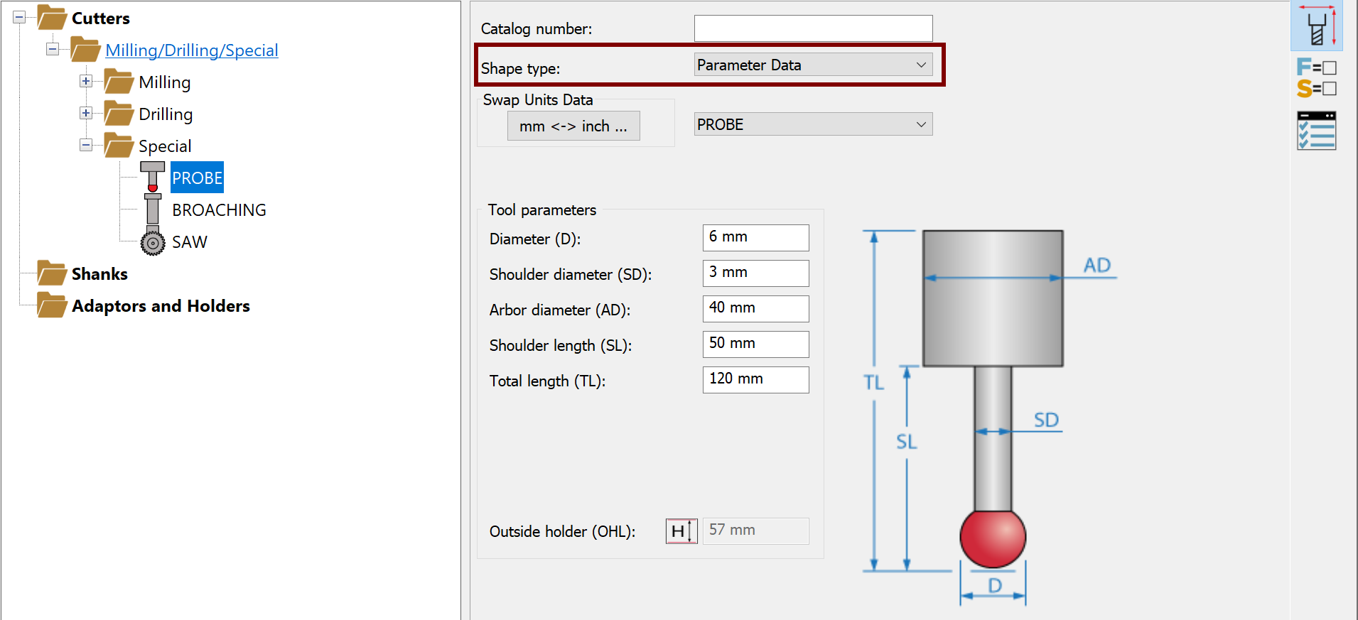
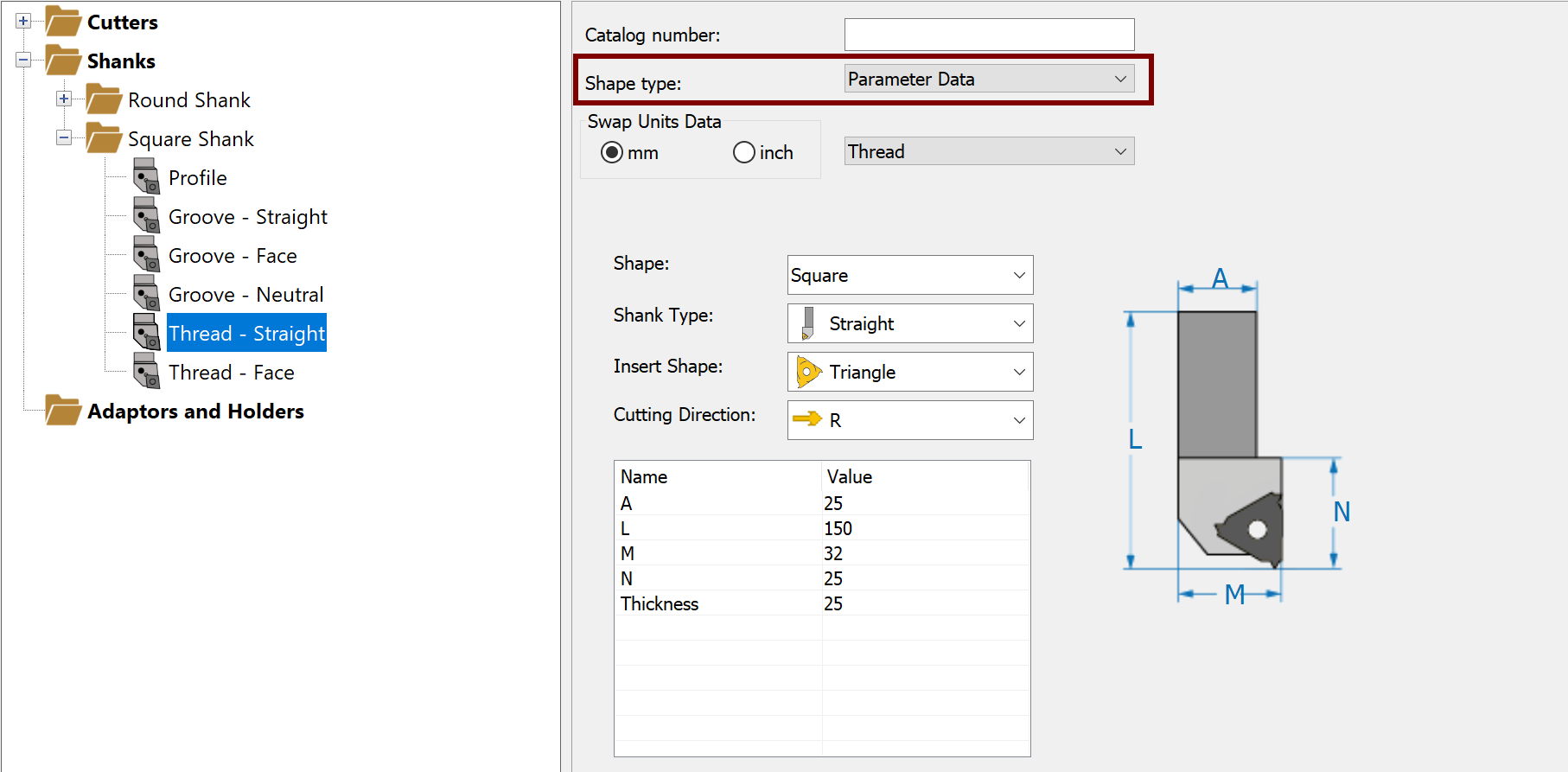
- For Milling, Drilling and Special Tools, the component can be defined by its dimensions using the Parameter Data pictured in the image.
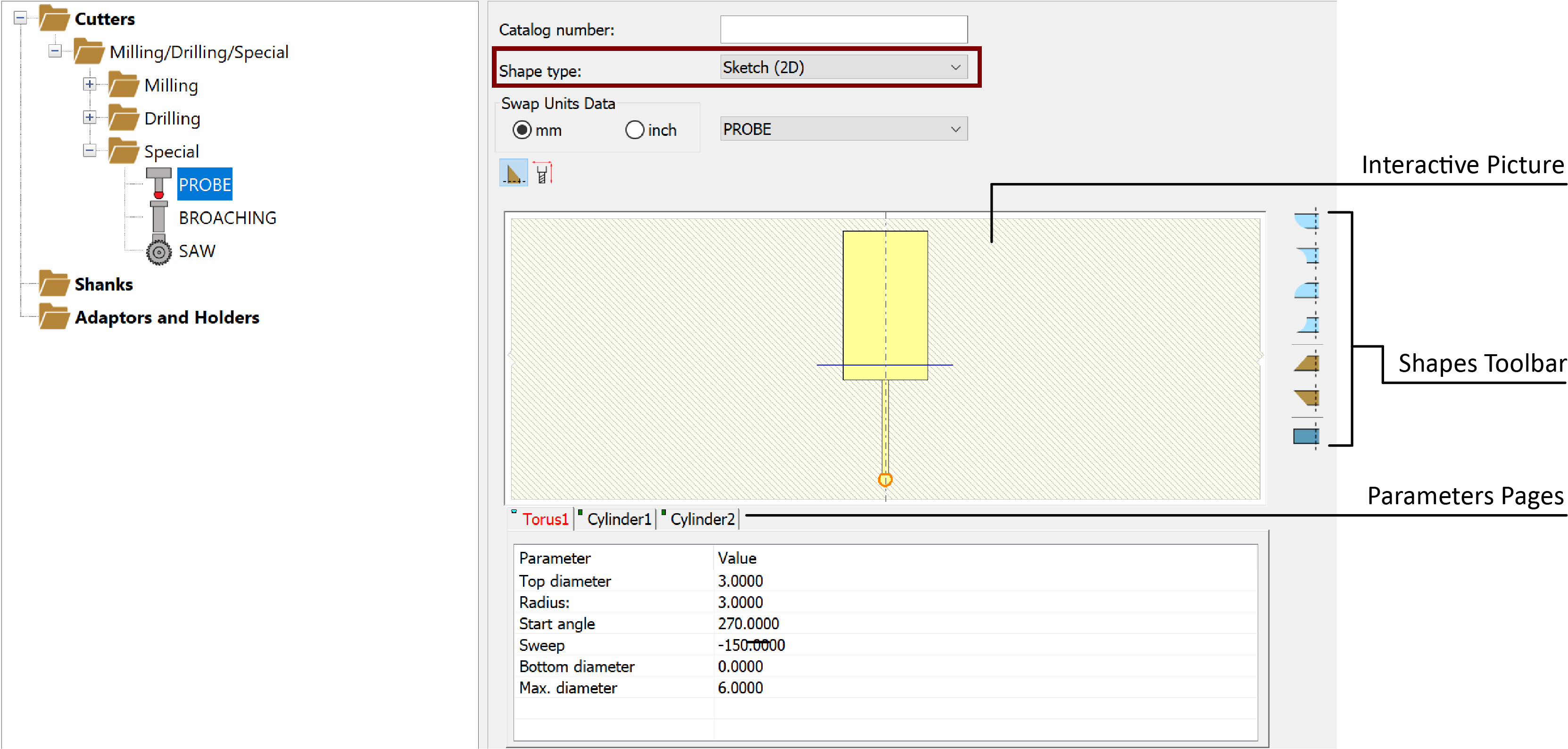
OR it can be defined via the Sketch (2D) option as shown below. Using this option, the Cutter component is defined by segment shapes such as cylinders, cones and toruses. Shapes can be added using the Toolbar or the interactive picture right-click commands. The actual dimensions can be edited by selecting the segments on the interactive picture and by using the corresponding Parameters pages.
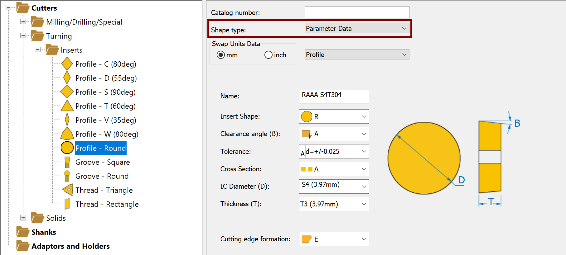
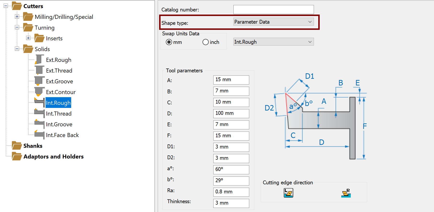
- For Turning Tools, whether an insert or a solid, the component can be defined using the Parameter Data only.
The Parameter Data definitions for insert tools will vary depending on the Tool Type (Profile, Groove or Thread) and Insert Shape (C, D, S, etc.).
The Parameter Data definitions are similar for solid tools of all types.
Shank components
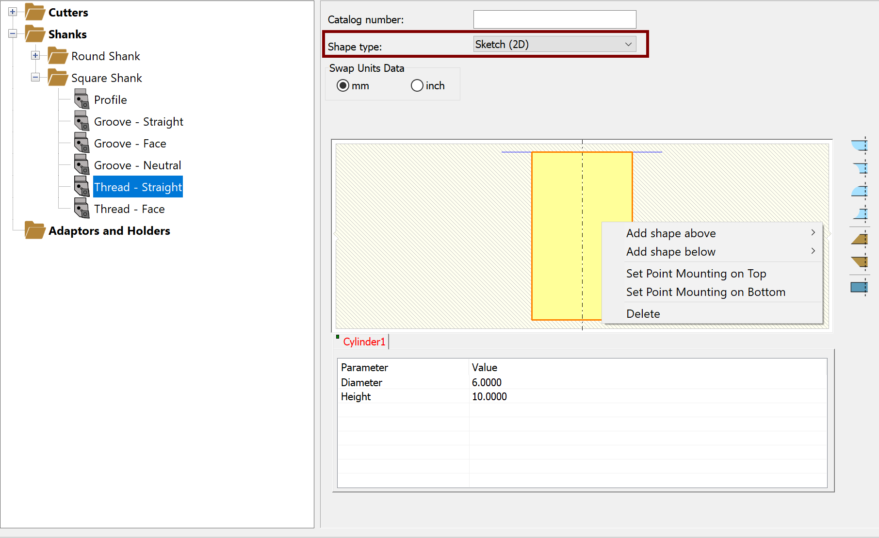
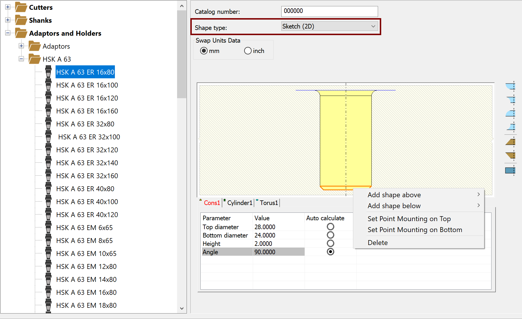
Shanks can be defined by one of three Shape type options: Parameter Data, Sketch (2D) or 3D Model (STL).
- Parameter Data specifies the Shank dimensions and, similar to Turning inserts, the parameters by which it is defined will vary depending on the Tool Type, Shank Type and Shape, and Insert Shape (for Profile and Thread types).
- Sketch (2D) specifies the Shank dimensions using segment shapes (similar to Milling, Drilling and Special Tool components).
- 3D Model (STL) defines the Shank component according to an STL or STEP file.
Clicking the ![]() button displays
the Select Shape file dialog box,
where you can browse for, select and Open the STL/STEP file of your choosing.
button displays
the Select Shape file dialog box,
where you can browse for, select and Open the STL/STEP file of your choosing.
You can add shapes using the interactive picture right-click commands or the Shapes Toolbar. The actual dimensions can be edited by selecting the segments on the interactive picture and by using the corresponding Parameters pages
Adaptor and Holder components
Adaptors and Holders can be defined by one of two Shape type options: Sketch (2D) or 3D Model (STL).
- Sketch (2D)
3D Model (STL) defines the Adaptor/Holder component by one or more STL/STEP files.
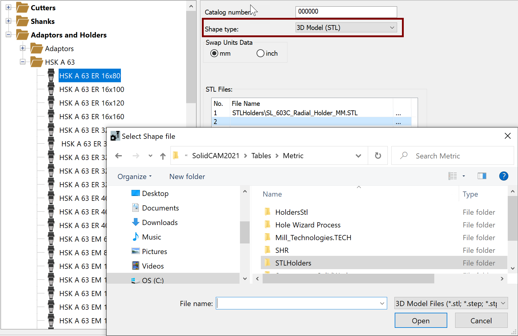
Each row in the STL Files table enables you to define an additional file.
|
To simplify your selections, default Shape types are set for the components as follows:
|
- After defining the component geometry, use the Data Toolbar and Data Page as needed to define the remaining properties.
Tool Components data
The Data Toolbar buttons and Data Page parameters and options will vary depending on your selection in the Database window.
All available Toolbar buttons and their functions are summarized here.
Continue adding and defining your components, organizing the Database folders to suit your needs, etc.
Once your Tool Components Library is ready, save it using the Save
 / Save and Exit
  buttons at the bottom right
corner of the TOOLKIT dialog box OR using the Save/Save As/Save
and Exit options in the ToolKit
main menu.
buttons at the bottom right
corner of the TOOLKIT dialog box OR using the Save/Save As/Save
and Exit options in the ToolKit
main menu.
Related Topics