Offset Data
![]()
Offset enables you to define the Cutting Point and Tool Preset data of the Tool Item as well as the relative Tool offset parameters for identifying its default position in the Tool Offset table of the CNC-Machine.
With the exception of Tool offset number and Tool offset index, the Offset button and its corresponding parameters are available only when Cutting point is selected in the Tool Item tree.
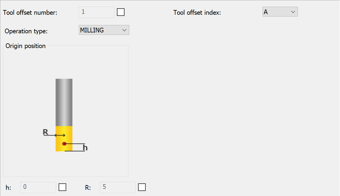
Operation type- This parameter represents the type of operation i.e. MILLING or TURNING, the tool could use. Select the required operation from the drop-down list.
Origin Position
h is height of the Cutting Point. The default value of h is 0.
R is the radius of the Tool. The default R value (R=D/2 or R=CD/2) is picked from the Tool Topology Data page.
SolidCAM offers you several possible locations for the tool origin position taking into account the h and R values from this section.
The Tool path in the Simulation always takes into account the h and R values from this section.
The tool origin position is defined by selecting the check box and adding the position/value of your choice.

SolidCAM allows you to change the values for h and R associated with the Cutting Point in the following operations:
For any other type of operations if you try changing the default h and R values, one of the following error messages is displayed:


Tool Preset
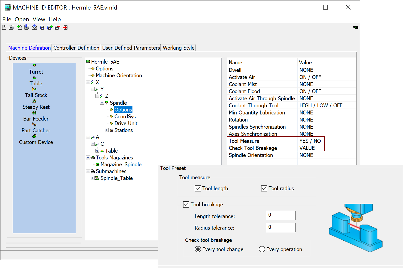
This section enables you to choose the options of the tool checking on a tool presetter.
In the Tool measure section, you can choose to check the Tool length and Tool radius.
In the Tool breakage section, when this option is selected, you can set your own values for the Length tolerance and Radius tolerance.
Length tolerance is defined as a maximal allowable difference between the measured and defined tool lengths.
Radius tolerance is defined as a maximal allowable difference between the measured and defined tool radiuses.
Check tool breakage
This option enables you to define how often the tool is checked for breakage: after Every tool change or after Every operation.
Tool Preset options are activated only if your CNC-Machine supports tool presetting and if, in the *.vmid file, Tool Measure and/or Check Tool Breakage for the Turret on which the Tool Item will be mounted is set accordingly. You can check this option in the Machine ID settings.
- Double-click the Machine name in the CAM Manager. The Machine ID Editor is displayed.
- Under Devices, locate the turret name that contains the tool you use. Expand the item.
- Click Options. On the right pane, make sure that Tool Measure is set to YES/NO. If this parameter is set to NONE, your CNC-Machine does not support tool presetting.
Multiple Cutting points
SolidCAM ToolKit supports multiple cutting points on a single Cutter component. If, for example, you want to use both top and bottom cutting faces of a SLOT MILL, another Cutting Point can be added using the Tool Item Manager.

(Swap Views shown for illustrative purposes)
In such cases, SolidCAM adds a replicated Tool Item with 0 h offset to the Tool Table list and assigns it the next available Tool offset index. When the Tool Item is modified, all shared properties are maintained.
Converting Tool offsets for ToolKit
When opening 2020 and earlier CAM-Parts in SolidCAM 2021, the Tool Offsets (from the classic Tool table) are converted as under:
- Tool offsets are represented as Cutting points in the TOOKIT dialog box.
- You cannot define a new cutting point inside operation (as in old Tool Table), you can only select pre-defined Cutting Point from the drop-down list.
- Conversion part to TOOLKIT will scan operations in CAM Part and add Cutting Points, if required.
- Conversion will vary for Milling, Turning, Grooving and T-Slot operations.
|
Terminology
|
Milling operations (does not include T-Slot operation)
User can use Cutting Points in the operation in the following ways:
i. Same Diameter and Length offset used from selected in operation Cutting Point.
ii. Length data used from additional Cutting Point, Diameter – from Selected in Operation
iii. Diameter data used from additional Cutting Point, Length – from Selected in Operation
iv. Both, Length and Diameter, are taken from different cutting points.
If User Defined Diameter or Length offset are not used in operation, the Default (First) Cutting Point of the tool will be used for this operation.
If User Defined Diameter offset number used in the Part and its number not equal to Operation Cutting Point number, additional Cutting Point with defined Offset Number will be created for this cutter. This point will contain same data as the initial (Default) Cutting Point (Diameter and H-Length). The Diameter value from this Cutting Point will be used for Tool Path calculation and G-code, but the H-length value will be taken from selected in operation Cutting Point or Length Offset, if it was defined. If the number is same as Operation Offset number, additional Cutting Point for cutter will not be created, but the check box near Diameter Offset should remain checked.
If User Defined Length offset number used in the Part and its number not equal to Operation Cutting Point number or Diameter Offset number, additional Cutting Point with defined Offset Number will be created for this cutter. This point will contain same data as the initial (Default) Cutting Point (Diameter and H-Length). The H-Length value from this Cutting Point will be used for Tool Path calculation, kinematic calculations and G-code, but the Diameter value will be taken from selected in operation Cutting Point or Diameter Offset number. It the number is same as Diameter Offset or Operation Offset, additional Cutting Point for cutter will not be created, but the check box near Length Offset should remain checked.
The Diameter Offsets field in Tool Data tab has been eliminated.
- The behavior for Diameter Offset number and Length Offset number is similar to above mentioned Milling operations.
- If Top tool offset number was defined, additional cutting point will be added to the cutter with H-Length value linked to Cutting Length.
- The Diameter Offsets field in Tool Data tab has been eliminated.
Turning operations (does not include Grooving)
- If User Defined Tool offset was used, additional cutting point will be created for cutter with related offset number. This Cutting point will used in the operation.
- The Offsets field in Tool Data tab has been eliminated.
Grooving operations
- Conversion process for User Defined Tool offset is same as for Turning operation.
- If second offset was used, additional cutting point will be created with relevant number.
Related Topics